This guide is based on the videos: How to create parts for KSP2 and How to make engines for KSP2 (see: [[Part modding videos (tutorials)]]), and on other notes and guidance from the KSP2 Modding Society discord.
[[Setting up Unity]]
The aim of this tutorial is to guide you through the process of creating your first '''part mod''' for Kerbal Space Program 2. We will go over everything from creating the part's mesh and textures to setting up the part in Unity to be bundled into a KSP2 mod.
Also the web pages: [https://luxstice.notion.site/KSP2-Part-tutorial-almost-from-scratch-1f336b7c97ae4280afb6a4e3aa6080b2 KSP2 Part tutorial (almost) from scratch], and [https://luxstice.notion.site/Tutorial-My-First-Part-5f0cf456d7f4443d8c92658c7cc58314 Tutorial: My First Part]
== '''Prerequisites''' ==
You will absolutely need the following things at a bare minimum:
* Unity Editor
* ThunderKit
* Unity KSP Tools
* Addressables Package (Install via Unity Window menu > Package Manager
** Change Packages to Unity Registry
** Search for “addressables”. Click on it and install.
You will generally also need the following things:
* Blender (or other mesh modeling SW that can produce FBX files)
* Various blender addons such as TexTools, etc.
* Substance Painter (or other texture painting tool – could be Blender or Quixel Mixer, but SP is highly recommended since there's a free integration to help make KSP parts)
You probably need a few other things too:
The way this tutorial will be structured is as a succession of steps which may link to other tutorials on this wiki, do not hesitate to keep this main page open while perusing the other tutorials. We aim at being as comprehensive as possible to enable you to make any part mod, but this page is still work in progress so stuff might be incomplete and/or subject to change in the future.
* JSON exports of similar stock parts to show you what some things can or should be set to
== Magnificent Mesh Modelling (Creating the part asset) ==
The first step in your part mod creation journey is to create the part's "3D asset", meaning its 3D mesh, textures and eventual animations. You can use any software you're comfortable with to do so but here are some guides for some specific software if you desire:
== Process ==
# [[Modeling the mesh in Blender]]
This guide covers the part of the process that takes place in the Unity Editor resulting in an assembly you can load as a codeless mod in KSP2, and how to get that result into the game.
# [[Texturing the mesh in Substance 3D Painter]]
# [[Preparing the mesh for Unity]]
In Unity editor start with a fresh scene. This will hold your entire parts pack.
Here are some resources that can be useful for modelling and texturing, regardless of the software you're using:
Part Pack Prep
* [[Sizes]]
* [[Texturing]]
== Part Pack Prep (Basic Unity part setup) ==
# '''Create Unity Project''': Create a new Unity project with an empty scene. You can use the sample scene.
# '''Create Unity Project''': Create a new Unity project with an empty scene. You can use the sample scene.
# '''Install Addressables package''': Open Window > Package Manger and select Packages: Unity Registry. Search for addressables and click Install.
# '''Install Addressables package''': Open Window > Package Manger and select Packages: Unity Registry. Search for addressables and click Install.
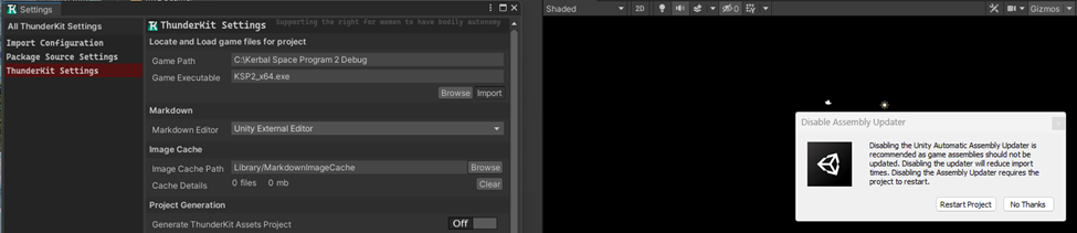
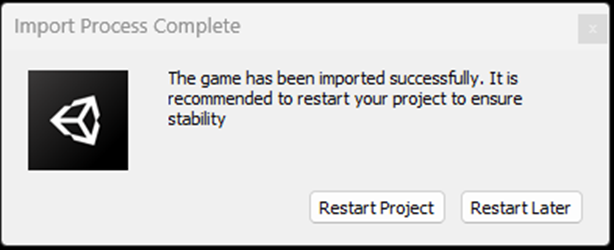
# [[File:Thunderkit Settings.png|alt=Thunderkit Settings|thumb|Figure 1: Thunderkit Settings]][[File:Import Process Complete dialog.png|thumb|Figure 2: Thunderkit: Import Process Complete]]'''Install ThunderKit in Unity'''. See [https://luxstice.notion.site/Installing-ThunderKit-7e00f13efe804f12a31a9f31d7f9fd6e Installing Tunderkit] from the Getting Ready section of the KSP2 Part Tutorial linked above for details. See figures for Thunderkit Settings and Thunderkit Import Process Complete for examples of what to expect in this process.
# '''Install ThunderKit in Unity'''. See [https://luxstice.notion.site/Installing-ThunderKit-7e00f13efe804f12a31a9f31d7f9fd6e Installing Tunderkit] from the Getting Ready section of the KSP2 Part Tutorial linked above for details. See figures for Thunderkit Settings and Thunderkit Import Process Complete for examples of what to expect in this process.
# '''Install Unity KSP Tools in Unity'''. See Installing KSP2 Unity Tools from the Getting Ready section of the KSP2 Part Tutorial linked above for details. KSP2 Unity Tools takes care of much of the initial setup for you, greatly streamlining the process while reducing the likelihood of errors with a single click <DESCRIBE WHAT NEEDS TO BE CLICKED>. <Describe KSP2 Unity Setup which takes care of swinfo, etc.>
# '''Install Unity KSP Tools in Unity'''. See Installing KSP2 Unity Tools from the Getting Ready section of the KSP2 Part Tutorial linked above for details. KSP2 Unity Tools takes care of much of the initial setup for you, greatly streamlining the process while reducing the likelihood of errors with a single click <DESCRIBE WHAT NEEDS TO BE CLICKED>. <Describe KSP2 Unity Setup which takes care of swinfo, etc.>[[File:Thunderkit Settings.png|alt=Thunderkit Settings|thumb|Figure 1: Thunderkit Settings]][[File:Import Process Complete dialog.png|thumb|Figure 2: Thunderkit: Import Process Complete]]
# '''Create Parts Pack folder''': Under Assets, create a folder (L-Click Assets: Create > Folder) and name it the same as your parts pack mod. If your mod is called My Awesome Mod then this would be Assets\MyAwesomeMod.
# '''Create Parts Pack folder''': Under Assets, create a folder (L-Click Assets: Create > Folder) and name it the same as your parts pack mod. If your mod is called My Awesome Mod then this would be Assets\MyAwesomeMod.
# '''Create Materials folder''': Inside your parts pack folder create a folder called Materials. You’ll be storing the textures and materials you need there. E.g., Assets\MyAwesomeMod\Materials. This is just to aid in organization.
# '''Create Materials folder''': Inside your parts pack folder create a folder called Materials. You’ll be storing the textures and materials you need there. E.g., Assets\MyAwesomeMod\Materials. This is just to aid in organization.
Line 247:
Line 234:
# '''Launch Game and Test!'''
# '''Launch Game and Test!'''
# '''''Rinse and Repeat for Additional Parts'''''
# '''''Rinse and Repeat for Additional Parts'''''
== '''Mentions''' ==
This guide is based on the videos: How to create parts for KSP2 and How to make engines for KSP2 (see: [[Part modding videos (tutorials)]]), and on other notes and guidance from the KSP2 Modding Society discord.
== Blender Basics for Beginners ==
Also the web pages: [https://luxstice.notion.site/KSP2-Part-tutorial-almost-from-scratch-1f336b7c97ae4280afb6a4e3aa6080b2 KSP2 Part tutorial (almost) from scratch], and [https://luxstice.notion.site/Tutorial-My-First-Part-5f0cf456d7f4443d8c92658c7cc58314 Tutorial: My First Part]
# If you’re making an engine, put an empty single arrow at the world origin facing in the direction your engine will fire, then move it along the axis of the engine so that it’s at the exit of the engine. Name this object thrustTransform, and keep in mind that size does not matter.
# Make sure all the part objects in your blend have the same material, and that the material has a good name. The material you use for this can be a default material, nothing special is needed.
# Make sure any Boolean modifiers are applied, but array modifiers can be left unapplied.
# Make sure you’ve got a good UV Map (use UV Smart Project) or an excellent one (UV Smart Project followed by Pack Islands). Recommended island spacing for both is 0.003
# When exporting your FBX for use in Substance Painter or any other tool, select only those objects that are actually part of your part and then be sure to check the box for Limit to Selected Objects
== Texturing Tips ==
# Make sure the Kerbal_Space_Program_2_Parts_Paintable.spt file is in your “Documents>Adobe>Substance Painter>Assets>templates” folder. If the templates folder doesn’t exist yet, then create one under Assets and drop that file in it.
# Launch Substance Painter and create a New project.
## In the project creation dialog pick the Kerbal_Space_Program_2_Parts_Paintable template
## Select your FBX file
## Make sure the Document Resolution is sufficient for your texture maps (highly recommend 4096! Any less and painted on bolts look like crap)
## Click Open ''<INSERT GRAPHIC HERE>''.
# Make sure the UV Map looks OK in Substance Painter. If it doesn’t, you need to go back to Blender and re-unwrap then export a new FBX and return to step 2 above.
# Use the File > Import resources… menu to bring up the Import Resources dialog (shown below) and click on the Add Resource button to bring in the KSP2_Part.spsm file. Repeat this step for the Kerbal Space Program 2 - Standard Damaged.spexp file. Both of these should go into your library as you’re going to need them with every part you make.
## Use the Add Resources button to find the resource you want to import
## Select the file and click the Open button
## Repeat steps (a) and (b) above for as many things as you would like to import
## Select the destination to Import your resources to (hint: library ‘your_assests’ for these!)
## Click Import ''<INSERT GRAPHIC HERE>.''
# Use the process in Step 4 above to bring in any textures you want to use. There are many you can peruse and download for free here: https://substance3d.adobe.com/community-assets
## Note: When importing textures, you can either put them in your library so that you can use them in multiple projects, or you can put them directly in your project if you don’t want them in your library. Either way works.
## You can repeat this step any time, and as often as needed, so don’t worry if you don’t have all the textures you need at the start. It’s also possible to make textures within Substance Painter
# Apply the KSP2 Part material to your whole object and once done delete the default later that Substance Painter provided.
# Locate the Bake button (looks like a croissant) in the upper right of Substance Painter and click it ''<INSERT GRAPHIC HERE>''.
## Uncheck the option to make an Opacity Mesh Map.
## Click the large blue Back Selected Textures button.
## When baking is done, click the Return to Painting Mode button.
# Expand the folder by the KSP2_Part smart material in the Layers panel.
# Expand the folder by the Base Material smart material within the KSP2 Part.
# Search for and select the materials you want to paint your part within the Assets panel.
## Drag a material from the Assets panel onto the Base Material in the Layers panel.
## Right click on that material and add a black mask to it, making sure the resulting mask is selected (there will be a blue border around it).
## Pick the Polygon Fill tool from the tool bar and then select a option from Triangle Fill, Polygon Fill, Mesh Fill, and UV Chunk Fill. ''<INSERT GRAPHIC HERE>'' Use the triangle to paint tris, the square (polygon) for quads, the cube (mesh) for entire objects, and the checkerboard (UV chunk) for connected faces on a side of surface.
# Create a simple material: Example white boron nitride ceramic.
## Click the Add Fill Layer button (paint can) ''<INSERT GRAPHIC HERE>''.
## Drag the new fill layer onto the Base Material folder.
## In the Propertied panel under Materials, leave only color, roughness, and metal selected.
## In the Properties panel set the base color to what you need (white in this case).
## Set the metallic slider to 1.0.
## Set the roughness slider to 0.3.
## Add a black mask to the fill layer.
## Paint like a pro.
# Add “Nails”: This is where you add various surface details via the height map, and works for painting on nuts, bolts, fasteners, etc. All of these can be added as “alphas” like this:
## Import your alpha(s)!
## In Layers, select the black mask for Nails in the Heightmap.
## Select Radial Symmetry (for applications around radially symmetric parts like I've got here).
## Set your X, Y, Z point about which things will be symmetric, where Y is the vertical. (Switch the Show/Hide Manipulator on to help see where this point is in your model).
## Set Mirror Y, the count you want, and the angular span the radial pattern should follow (360 for all the way around).
## With the brush tool active, select your alpha.
## Move your cursor onto the part and see the red dots where the "Nails" will be placed.
## Adjust the size of the "Nail" using [ and ] to make it smaller or larger respectively.
## Click where you want the first "Nail" to appear, this will place them all.
# Add “Stickers”: This is where you add signs, stickers, decals, etc., where the sticker has a uniform color (like a radiation symbol, etc.).
## Import your alpha(s)!
## In Layers, under Base Material, add a fill layer for the sticker.
### Uncheck all material properties for the layer except color, metal, and rough.
### Set the fill color to be what you want the sticker to look like.
### Move the layer to be above any other Base Material layer that impacts the part(s) you’re going to apply stickers to (or it will be overwritten and you won’t see your stickers!)
## Select Radial Symmetry (for applications around radially symmetric parts like I've got here).
## Set your X, Y, Z point about which things will be symmetric, where Y is the vertical. (Switch the Show/Hide Manipulator on to help see where this point is in your model).
## Set Mirror Y, the count you want, and the angular span the radial pattern should follow (360 for all the way around).
## With the brush tool active, select your alpha.
## Move your cursor onto the part and see the red dots where the "Stickers" will be placed.
## Adjust the size of the "Sticker" using [ and ] to make it smaller or larger respectively.
## Click where you want the first "Sticker" to appear, this will place them all.
The aim of this tutorial is to guide you through the process of creating your first part mod for Kerbal Space Program 2. We will go over everything from creating the part's mesh and textures to setting up the part in Unity to be bundled into a KSP2 mod.
The way this tutorial will be structured is as a succession of steps which may link to other tutorials on this wiki, do not hesitate to keep this main page open while perusing the other tutorials. We aim at being as comprehensive as possible to enable you to make any part mod, but this page is still work in progress so stuff might be incomplete and/or subject to change in the future.
Magnificent Mesh Modelling (Creating the part asset)
The first step in your part mod creation journey is to create the part's "3D asset", meaning its 3D mesh, textures and eventual animations. You can use any software you're comfortable with to do so but here are some guides for some specific software if you desire:
Create Unity Project: Create a new Unity project with an empty scene. You can use the sample scene.
Install Addressables package: Open Window > Package Manger and select Packages: Unity Registry. Search for addressables and click Install.
Install ThunderKit in Unity. See Installing Tunderkit from the Getting Ready section of the KSP2 Part Tutorial linked above for details. See figures for Thunderkit Settings and Thunderkit Import Process Complete for examples of what to expect in this process.
Install Unity KSP Tools in Unity. See Installing KSP2 Unity Tools from the Getting Ready section of the KSP2 Part Tutorial linked above for details. KSP2 Unity Tools takes care of much of the initial setup for you, greatly streamlining the process while reducing the likelihood of errors with a single click <DESCRIBE WHAT NEEDS TO BE CLICKED>. <Describe KSP2 Unity Setup which takes care of swinfo, etc.>Figure 1: Thunderkit SettingsFigure 2: Thunderkit: Import Process Complete
Create Parts Pack folder: Under Assets, create a folder (L-Click Assets: Create > Folder) and name it the same as your parts pack mod. If your mod is called My Awesome Mod then this would be Assets\MyAwesomeMod.
Create Materials folder: Inside your parts pack folder create a folder called Materials. You’ll be storing the textures and materials you need there. E.g., Assets\MyAwesomeMod\Materials. This is just to aid in organization.
Create Parts folder: Inside your parts pack folder create a folder called Parts. You’ll be storing the part meshes and related things there. E.g., Assets\MyAwesomeMod\Parts. You can have whatever organization you like here, so if you want to group some parts you might create group folders within Parts (e.g., Methalox Engines, Nuclear Engines, Ion Engines, etc.). This is just to aid in organization and is optional.
Create Plugin Folder and Content: In your Unity project's Assets\plugin_template folder create a “localizations” folder. NOTE! This is currently required to be exactly this – localizations (plural), not localization (singular). This will be where you put the localization files (e.g., english.csv, spanish.csv, etc.).
Create Localization file(s): Localization files are CSV files following a particular format. These must have lines ending with LF not LF/NL, and they must reference the same <part_name> you use in the Part Production process below. There are some other restrictions for content, particularly that if you want a string that contains a “,” that string needs to be enclosed in quotes or the comma will mess with how the strings are parsed. These files are where the part’s Title, Subtitle, Manufacturer, and Description are configured. Here’s an example:
Key,Type,Desc,English

Parts/Title/spark_spt100,Text,,SPT-100

Parts/Subtitle/ spark_spt100,Text,,Hall Effect Thruster with Xenon Tank

Parts/Manufacturer/spark_spt100,Text,,"Stellar Plasma-Assisted Rocket Kinetics, inc."

Parts/Description/spark_spt100,Text,,"The SPT-100 is the pinnacle in tiny (0.625m-class) Ion engines, providing high Isp and low thrust with an integral toroidal xenon tank. Strap this little guy onto a probe core and be sure to bring plenty of electrons because you're in for a long slow ride to anywhere!"

Parts/Title/spark_x3,Text,,X3 NHT

Parts/Subtitle/spark_x3,Text,,Three-Channel Nested Hall Effect Thruster

Parts/Manufacturer/spark_x3,Text,,"Stellar Plasma-Assisted Rocket Kinetics, inc."

Parts/Description/spark_x3,Text,,"The SPARK X3 is the pinnacle in small (1.25m-class) Ion engines, providing high Isp and low thrust. Strap this bad boy onto your large probe or small capsule and be sure to bring plenty of electrons because you're in for a long slow ride to anywhere!"
Part Production
Create Root Part Object: Create an empty game object under your scene (L-click Scene: Game Object > Create Empty). Name this object the same as your part.
Recommended naming scheme: <mod_name>_<part_name>. If your mod is called “My Awesome Mod” and your part title is “My Part”, then your part name might be my_awesome_mod_my_part for example. Part names must be unique, though you can have any descriptive title you like (that is done later in Localization). A naming scheme like this helps to prevent naming collisions in case anyone else might make a part they want to call “My Part”, like yours.
Create Model Object: Create an empty game object under your root part object and name this one “model”.
Create Part Folder: Create a Part folder named for your part inside your Parts folder. E.g., Assets\MyAwesomeMod\Parts\MyPart, or Assets\MyAwesomeMod\Parts\ThisGroup\MyPart if you’re grouping parts.
Bring in FBX: Drag a copy of your part’s FBX file into the part folder.
If you have baked textures for your part that go with the FBX (meaning, they’re based on the UV Unwrap specific to that FBX), then drag those into this same file with the FBX.
Create Part Object: Drag a copy of the part FBX from the Part folder in Unity to the model object created in step 2. Don’t drag the FBX file from your computer’s files system, you need to use the copy you just placed in step 4. This will create a prefab for your part as a child of the model object.
Unpack Prefab: Left-Click part object: Prefab > Unpack.
Remove Unnecessary Things: Remove any parts that came in with the FBX that you don’t actually need in the game like lights, cameras, empty nodes, etc. If it’s not an actual part you want the game to render, then delete it.
Orient Part: Your model will appear in the Unity scene oriented as you built it in Blender, but this may not be the way you want it to be oriented in the game. If you need changes to the position, rotation, or scale of the part do those now using the Transform panel within the Inspector Window with your part object selected. For example, to flip a part over just give a rotation of 180 in Z, etc.
Create Mesh Object: L-Click part object: Create Empty. Name this object “mesh”.
Create Collider Object: L-Click mesh object: Create Empty. Name this object “col”.
Create Collider: In the Inspector window for the col object click “Add Component”. Search for Mesh Collider and pick it. This will create a Mesh Collider component in the col object. Click the arrowhead to the left of it to expand it and see its properties.
Select Mesh: In the Mesh Collider properties select the Mesh you want to use. If your FBX is all one object you can pick that, or you can pick a suitable primitive like cube or cylinder, etc.
Position, Rotation, and Scale: Set the position, rotation, and scale of the mesh to encompass the part. You should see a green mesh represented in the Scene window to help guide you to make sure you’ve got the right position, rotation, and scale.
Convex: Check “Convex”
Add Core Part Data: Select your Root Part Object. In the Inspector Window click “Add Component”. Search for “Core Part Data” and pick that. Open it up and configure as follows:
Part Name: The Part Name needs to be the same as what you’ve used for the Root Part object, i.e., my_awesome_mod_my_part or whatever you used.
Author: Use what you like here, typically your KSP Forum screen name or whatever you go by as your modding author name.
Category: Select an appropriate category for your part.
Family: If you wish to identify a “Family” for your part, this needs to be a particular string. You can find examples in the game’s files, or part JSONS, or ask in the KSP2 Modding Society discord to get this information.
Co Lift, Co Mass, Co Pressure, etc.: These parameters allow you to set the Center of Lift, Center of Mass, Center of Pressure, etc. Adjust these to get the markers in the Unity scene where they should be for your part. Typically, Co Pressure and Co Lift are in the same place.
Fuel Cross Feed: Check if fuel should be able to transit through your part on the way to other parts. Typically set to true, but not always.
Mass: Set this in metric tons, not Kg.
Attach Rules: Check the types of attachment your part should allow. Checking “Stack” or “Srf Attach” will allow your part to attach in a stack or to a surface. Checking “Allow Stack”, “Allow Srf Attach”, etc. will allow other parts to stack attach or surface attach respectively. Currently (?) Allow Collision, Allow Dock, Allow Rotate, and Allow Root have no effect in game (check this).
Attach Nodes: If Stack is checked above, then you need a “top” and a “bottom” node, if Srf Attach is checked above, then you need a “srfAttach” node. Note, node names are case sensitive and having a node is not enough by itself, you do also need the corresponding Attach Rule set true or the node will have no effect. Under Attach Nodes click the + button to add a blank node and configure as needed.
Node ID: “top”, “bottom”, “srfAttach”, etc. (case sensitive!)
Node Type: Select as appropriate. (Stack for Stack, Surface for Surface…)
Attach Method: Select Fixed_Joint for Stack and Hinge_Joint for Surface Attach.
Is Multi Joint: In general set to True for stack attach to help prevent noodle rockets.
Multi Joint Max Joint: Set to 3 if you set Is Multi Joint to true?
Position: Set as appropriate. Should be on the skin or outside of the part where you would expect to find it on your part in the VAB.
Orientation: Set as appropriate. The Orientation vector should be a unit vector (length 1) pointing in the direction of the part that will attach to the node, so pointing away from your part.
Size: Affects rigidity of your part. If your part is connected to another part with the same “size” node, then rigidity will be optimal, and otherwise it will be suboptimal.
Visual Size: Set the same as Size.
Is Resource Crossfeed: Set as needed for this node.
Is Rigid: Set as needed for this node.
Rinse and Repeat: Subsequent nodes created with the + button will inherit settings from the last node made, so this may accelerate the process as you just need to change the Node Id, Position and Orientation for new nodes that are similar to the previous created node.
Add Module_Color: You need this to be able to paint your part with base and accent colors. As above, click Add Component and search for Module Color.
Add Module_Drag: All parts need this. As above, click Add Component and search for Module Color.
Add other modules as needed. For example, if your part is an engine you’ll also need:
thrustTransform object: Create an empty game object as a child of the root part and name it thrustTransform.
Throttle VFX Manager: Configure as needed (?). No need to drag anywhere, it just need to be a component for the part.
Flameout VFX Data: Drag this up to the Flameout VFX property in Module_Engine.
Module_Gimbal: Configure details as needed (e.g., Gimbal Range and Gimbal Speed, etc.), then drag this up to the Gimbal property in Module_Engine.
Module_Generator: Configure details as needed, then drag this up to the Alternator property in Module_Engine.
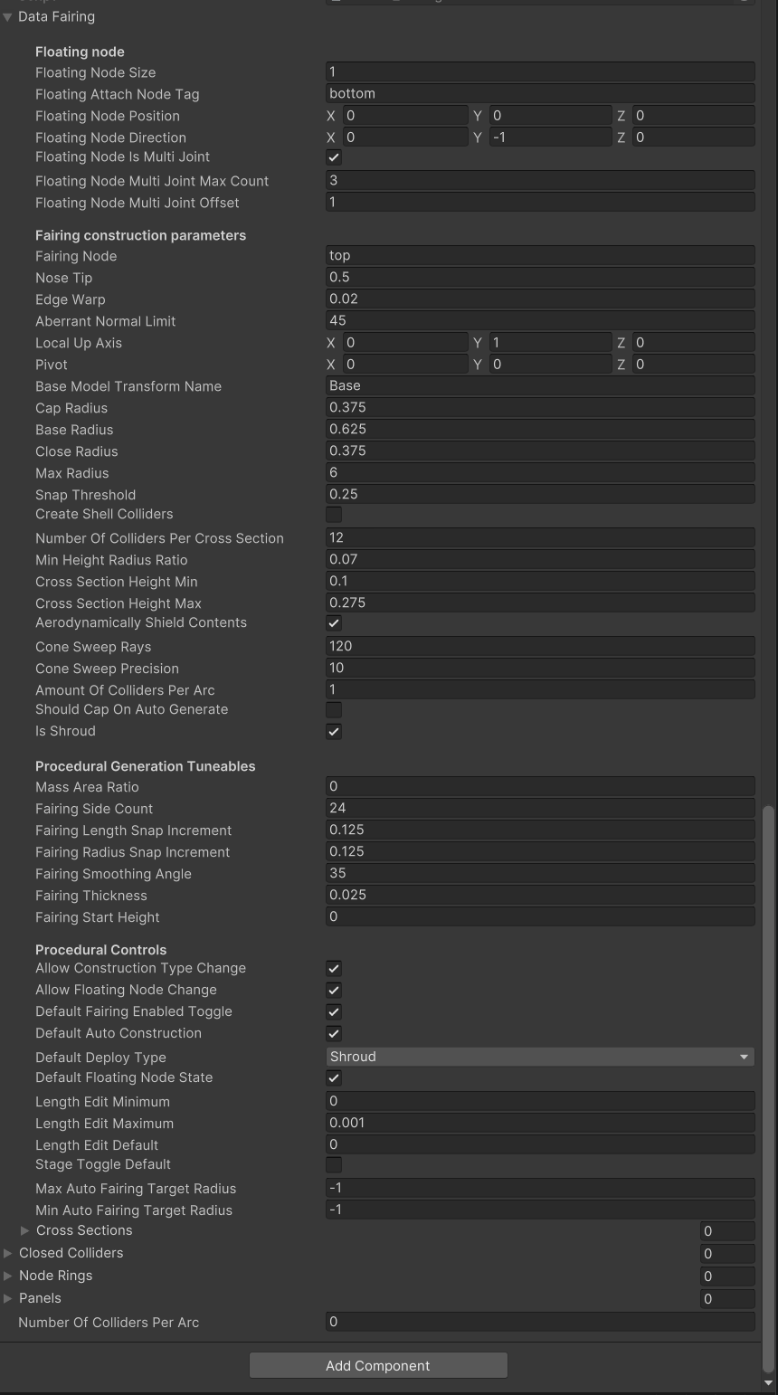
Figure 3: Example Fairing Data in Unity EditorModule_Fairing: Unless you plan for your engine to only ever be on the very first stage (i.e., a big booster), then you probably want it to have a fairing so it can be used in the second stage and above. Figure 3 shows an example for a working fairing from a Size Small (1.25m-class) engine that was created using this process. Shown below is the corresponding example of the PartComponentModule_Fairing portion of the part JSON. As can be seen in Figure 3, the data fields that need to be populated in the Unity Editor include only a subset of what's in the auto-generated JSON. That said, everything the editor needs is in the example below and presenting it this way makes copy/paste possible where unity editor graphic would not allow that.
Of the information show above, the parts you will most likely need to customize for your fairing are Base Radius, Cross Section Height Max, and Fairing Thickness - the rest is likely to be the same for all your engines with one other important thing to note. The example above is for an engine that was made in Blender with the nozzle bell facing upwards. If your engine was made with the nozzle bell facing down, then you will need the Local Up Axis to be -1 in Y and you will also need set the Fairing Node to bottom.
Apply Options: Select the root part and in the Inspector window near the top on the Prefab line, click the Overrides dropdown and pick “Apply All”. If this option is not available, then you’ve got nothing you need to do here. Move along, move along.
Save Part JSON: Click Save Part JSON button at the bottom of the Core Part Data module. This will put the resulting part JSON in the Assets folder for your Unity project. You need to do this any time you’ve edited the Core Part Data module (or also a module it depends on?).
Make Prefab: Grab the root part object and drag it to the Unity project Assets folder.
Add Part Icon: Create an icon for your part that the game will use in the parts picker. This needs to be a PNG file with specific dimensions. It should conform to the style used by other parts in the game. However you do this, you need to name the file <part_name>_icon.png, and you need to drag that file into the Assets folder in Unity.
Convert Icon to Sprite: Select the part icon in the Assets folder. In the Inspector window, click the pulldown menu for Texture Type and change this from Default to Sprite (2D and UI), then click Apply. If this is not done, your lovely icon will not display!
Make Root Part Addressable: Select the root part’s prefab in the Assets folder and in the Inspector window check the box for Addressable.
Make JSON Addressable: Select the part’s JSON in the Assets folder and in the Inspector window check the box for Addressable.
Make the Icon Addressable: Select the root part’s icon in the Assets folder and in the Inspector window check the box for Addressable.
Configure Addressable Properties: In the Addressables Groups expand the Default Local Group and find your part.
Group Name \ Addressable Name: Change the information in the Group Name \ Addressable Name from “Assets/<part_name>*” to be just “<part_name>*”. So “Assets/<part_name>.prefab” becomes “<part_name>.prefab”, and so forth. You can leave the “Assets/” part of the path definition alone for each of these, that’s as it should be. The value for the Addressable Name needs to be the same as the file name it’s associated with and must not include any path parts. All of these need to be based on the Part Name established in the Core Part Data module.
Labels: For the JSON set this to parts_data. Leave it blank for the prefab. If parts_data is not an option in the dropdown for Labels, then click Manage Labels, click the + button to add a new label, and set the Label Name to “parts_data”. Click Save.
Build Mod or Build And Test: Select either Build Mod or Build And Test to have KSP2 Unity Tools prepare and deploy your parts pack mod.
Launch Game and Test!
Rinse and Repeat for Additional Parts
Mentions
This guide is based on the videos: How to create parts for KSP2 and How to make engines for KSP2 (see: Part modding videos (tutorials)), and on other notes and guidance from the KSP2 Modding Society discord.